


General steel detailing process
Steel detailing is the process of producing a set of fabrication drawings which are relied upon for the production of steelwork.
In basic terms, architects design the building (size, finishes, materials etc.). Structural Engineers calculate, design and specify the structural elements. Both of these disciplines convey this information in drawings. Steel fabricators cannot fabricate their steel from architects or structural engineers drawings. To fabricate steel one requires Fabrication Drawings.
Fabrication Drawings are derived from a combination of the architectural & structural engineers drawings. The setting out of the steel (in plan and elevation) is taken from the architects’ drawings and the sizes as well as the connections from the structural engineer’s drawings.
Drawing requirements
The steel detailer needs to convey sufficient information on the fabrication drawings to allow the fabricator to produce the required steel without any queries.
General Assembly Drawing
It is common practice that a General Assembly drawing is produced first for comment and approval. 3D CAD Modelling is now the standard for steel detailing. This means the GA drawing is derived from the 3D CAD model.
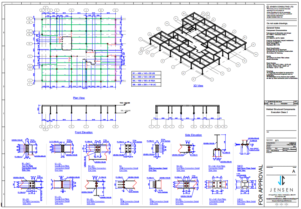
The General Assembly drawing has to communicate sufficient detail to allow the structural engineers and architects an excellent understanding of the steel model without any assumptions being made.
The GA drawing should show:
- Plan view, fully dimensioning all column and beam positions
- Elevations & sections showing top of steel (TOS) heights
- All steel connections in detail views
- All section sizes
- Material type of all sections (hot & cold rolled) and plates
- Finish (such as galvanised or primed)
Once the GA drawing has been approved by the structural engineer and architect the detailed fabrication drawings can be produced. There is no point for the detailed drawings to be produced prior approval and fabrication should never commence prior approval of the GA.
General Assembly Drawing – Structural Steel – Steel Detailing
The detailed fabrication drawings mainly consist of Assembly Drawings & Single Part Drawings. It seems that fabricators have different preferences whether they find Single Part drawings helpful. For smaller projects, there seems to be a common opinion that fully dimensioned Assembly Drawings will suffice as the combination of Assembly & Single Part drawings simply results in too many drawings.
Assembly Drawing
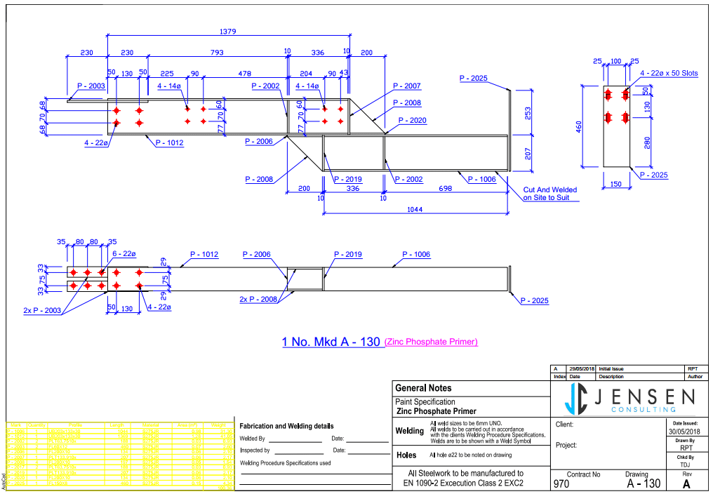
Assembly Drawings show the welded item made up of different single parts. A typical beam assembly often consists of a beam and a few plates which are welded to the beam. Assembly drawings will not necessarily show all the plate dimensions but have to be dimensioned in a manner that will allow all parts (plates and beams) to be welded together.
Single Part Drawing
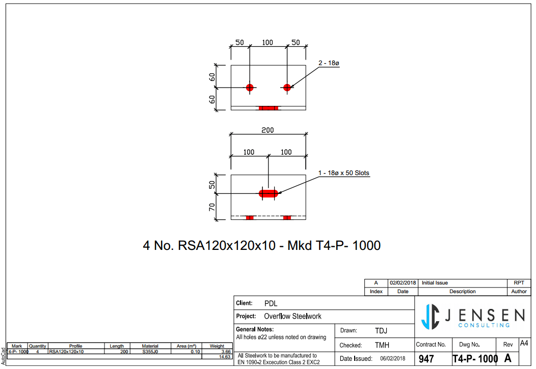
Single Part Drawings only show one fully dimensioned part. This can be a plate or a beam.
Dimensions & labeling
Dimensioning standards of structural steel differ from machine/manufacturing drawing dimensioning. The same rules do not apply. The major difference to manufacturing drawings compared to fabrication drawings is that the golden rule is not to double dimension manufacturing drawing does not need to be adhered to on fabrication drawings.
General Assembly Drawing
In order to get the fabrication drawings approved, a GA drawing is submitted for approval. This GA drawing needs to show:
- A dimensioned grid (preferably the same as the architects’ grid)
- All beam positions dimensioned to each other and the grid
- All column positions dimensioned to each other and the grid
- Typical connections dimensioned and plate sizes, as well as bolt types, labeled
- TOS heights labeled, preferably using the same datum as the architect
- Steel section sizes labeled for all column, beams and bracing
Once approval of the GA drawing has been gained the GA drawing is then revised to a construction issue. The construction issue will additionally state the assembly number of each beam to assist with the erection. Additional views can be added to the GA in order to assist the steel erection team. This type of GA drawings is also referred to as a Steel Erection Drawing.
Assembly Drawings
Assembly drawings should be dimensioned and labeled in a way to allow the welder to assemble and weld all parts together. This means an assembly drawing should show:
- Plate and beam positions dimensioned to each other.
- All parts should be dimensioned on visible views. No hidden lines should be dimensioned if possible. Additional views should be added to avoid this.
- Running dimensioning are preferred by many welders
- Hole size and position (hole size often only needs adding if it is not 22mm, standard hole size needs to be stated in the notes)
- Weld type and size (weld size often only needs adding if it differs from the standard weld stated in the notes)
- All part numbers need to be labeled for each part
- The finish is stated on each drawing (such as galvanised or primed)
Assembly Drawing – Structural Steel – Steel Detailing
Single Part Drawings
Single Part Drawings should be dimensioned and labeled in a clear way to allow cutting and punching of holes without any queries or assumptions. The single part drawings should state:
- Size (width, height, depth) of all cuts dimensioned
- The position of all holes dimensioned
- Section size stated on drawing – not dimensioned
- The overall quantity of each part
Single Part Drawing – Structural Steel – Steel Detailing
Building Regulations
In the UK, Approved Document A relates to structures. It is important to recognise that the regulatory system in the UK is such that the Building Regulations themselves merely make high-level demands, for example, that a structure is safe. Use of the standards cited in Approved Document A is only one way to demonstrate that requirement has been met.
Design codes & standards
There are ten separate Structural Eurocodes:
- EN 1990 Eurocode: Basis of structural design
- EN 1991 Eurocode 1: Actions on structures
- EN 1992 Eurocode 2: Design of concrete structures
- EN 1993 Eurocode 3: Design of steel structures
- EN 1994 Eurocode 4: Design of composite steel and concrete structures
- EN 1995 Eurocode 5: Design of timber structures
- EN 1996 Eurocode 6: Design of masonry structures
- EN 1997 Eurocode 7: Geotechnical design
- EN 1998 Eurocode 8: Design of structures for earthquake resistance
- EN 1999 Eurocode 9: Design of Aluminium Structures
Each Eurocode comprises a number of ‘Parts’, which are published as separate documents. Each Part consists of the main body of text, normative annexes, and informative annexes (the ‘relevance’ of which is decided on a national basis).
For a steel detailer, Eurocode 3 is the most relevant and helpful. As often, it is the steel detailers scope to design the joints, the green book Simple joints to Eurocode 3 is most helpful and should be adhered to.
Computer Aided Design (CAD) software
There are a few dedicated steel detailing CAD software packages available. Steel detailers should only use dedicated steel cad packages to produce fabrication drawings. Sketchup or 2D AutoCAD are not sufficient or efficient.
3D CAD is now the standard for steel detailing. The main packages used are Tekla and Advance Steel.
Summary
Steel detailing should only be carried out by professional steel detailers. Structural steel designed and drawn wrong can have lethal consequences at worst or just be very costly to rectify at best ลิงค์ของฉัน.
Standards need to be adhered to using the right people and software.
For professional fabrication drawings, generated by qualified steel detailers please contact Restoric Design on 01462 514 300 or email info@jensen-consulting.co.uk
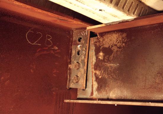
Failed Structural Steel Connection
Abbreviations
TOS: Top of steel
GA: General Assembly
CAD: Computer Aided Design
Resources
https://www.steelconstruction.info/Design_codes_and_standards
http://911research.wtc7.net/mirrors/guardian2/fire/cardington.htm