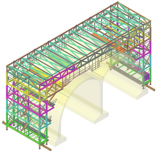
Computer aided design (CAD) software is a program that combines hardware and software platforms used by developers for the development and documentation of physical objects. Currently, MicroStation and AutoCAD are the most widely used common purpose CAD platforms. Organizations engaged in architecture, engineering, surveying, and construction use these applications to provide various services.
Advantages of computer aided design programs
The main goal of the development of computer aided design programs is to increase the efficiency of engineering labour. Below are some advantages of using computer aided design and drafting programs.
• CAD programs facilitate the design process for employees of all industries.
• They help engineers to complete their projects on time.
• They reduce the initial cost of design work by eliminating the expenses and remuneration of many hours of workers labour.
• CAD programs improve the quality of the finished product at each particular stage.
• CAD programs help engineers to collect and classify documents automatically.
• These programs have quick decision libraries for quick decision making.
Types of computer aided design programs
1. 2D CAD programs
By their capabilities, they fully cover the 2D CAD and also allow you to work with assemblies, in some respects, they are no longer inferior to 3D CAD programs and even surpass them in the convenience of work. These are not just programs, but software systems, in particular. Examples of these CAD systems include SolidWorks SolidEdge, Cimatron, Form-Z, Autodesk Inventor and CAD SolidMaster.
2. 3D CAD programs
These systems are used to solve the most difficult tasks. They model the behaviour of complex mechanical systems in real time, optimize calculations with visualization of results, calculate fields temperature and heat transfer. Usually, they include both pure graphics modules for carrying out calculations and modelling. Unfortunately, these CAD systems are the most cumbersome and complicated programs to use. They also have a significant cost. Examples of 3D CAD systems include ADAMS, ANSYS, CATIA, EUCLID3, Pro / ENGINEER and Unigraphics.
3D CAD models
a) Surface CAD models – These 3D Computer Aided Designs programs are used to create models by joining 3D surfaces. They are quite realistic because nothing is visible in the background.
b) Wire-frame CAD models – These types of 3D CAD programs are used to create skeletons like models with arcs and lines. Everything in their background is visible.
c) Solid CAD models – These are the most used 3D Computer Aided Design models. They resemble surface models but have additional properties such as density, weight, and volume.
Types of CAD drawings
Computer-aided design software can be used in a variety of ways. Below are several simple drawings and designs that one can make using CAD software.
1. Floor plans
Computer-aided design programs are used to draw floors plan diagrams that help to visualize homes and buildings. These scaled diagrams show the placement, size, and shape of rooms and other different objects within the structure using a top-down view.
2. Technical drawings and blueprints
A technical drawing is a highly detailed and scaled plan of an object. With the help of a Computer Aided Design program, engineers can draw technical diagrams that are used to convey exact specifications of how something is supposed to appear. Technical drawings are used in mechanical, engineering and architectural designs.
3. Creating instrumentation and piping diagrams
Engineers use CAD software to draw instrumentation and piping drawing that show the relationships between instrumentation, piping and other elements of a physical flow process.
4. Creating HVAC drawings
Computer Aided Design programs are used to draw Heating, ventilation, and air conditioning diagrams that provide information about heating, ventilation and air conditioning systems in a given location. These diagrams capture the location and size of ductwork, control units connections, together with the relationship between various components.


