


General
Flats, angles, channels, I sections, and hollow sections can be used for bracing. Bracing can be in tension or in tension & compression. In most cases, bracing is attached via a lapping joint to a gusset plate. The gusset plate is preferably welded to the section and its end connection.

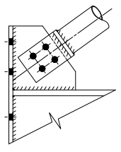
Typical Bracing Connection
Centre Lines & Node Points
It is usually assumed that all forces intersect on member centrelines. However, this might result in very large gusset plates. The intersection can potentially be moved but local member checks have to then be included looking at the effects of eccentricities which are introduced.
Sections
Flatbar and angles are commonly used for tension only braces
Hollow sections are used where both tension and compression exist. For hollow sections, typically CHS sections are connected via a fabricated “T”. For light loads, the “T” shape is to be used. For heavier loads, the plate can be connected to the member. However, this results in higher fabrication cost (to be checked with fabricator).
Gusset Plates
Gusset Plates in compression should preferably be supported on two edges and be as small as possible. This might require moving the intersection point (a check for resulting effects of eccentricity is then required).
Plate thickness should be generous but keep to standard plate thicknesses.
Option 1:
The section centrelines intersect and the gusset plate is connected on two sides. This is the preferred option.
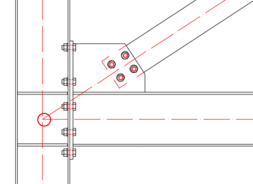
Intersecting Centrelines

The stress distribution is even and the peek stresses are kept to a minimum.

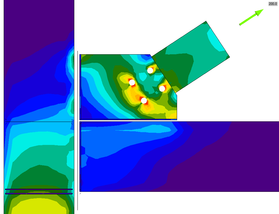
Stress Distribution – Intersecting Centrelines
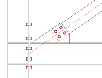
Option 2
The intersection is moved to the top of the beam but the gusset is still welded on two sides. The column and beam need to be checked for the additional moment that has been introduced.
Centreline top of the beam

The intersection at the top of the beam creates moments in the beam and column as can be seen with the additional stresses in these areas.

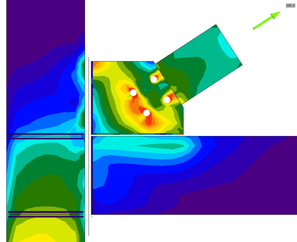
Stress distribution – Centreline top of the beam
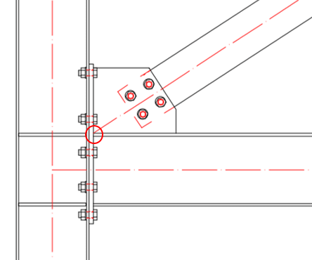
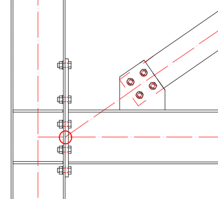
Option 3
This method should only be used for light loads. The column needs to be checked for the additional moment that has been introduced.
Centreline column flange

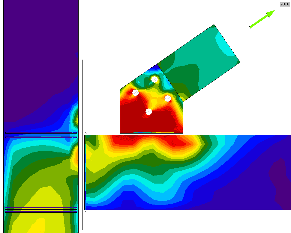
This method results in additional stresses in the beam. Especially the stress resulting from the shear loads at the bolt locations in the beam.

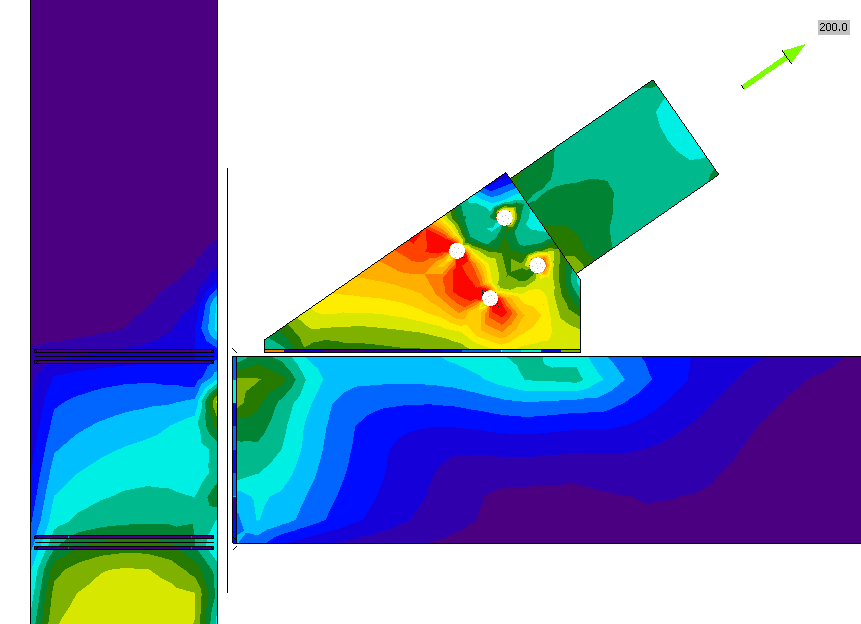
Stress distribution – Centreline column flange
Not an option
This method should not be used in any case. Many detailing software packages create this connection as standard however it is not advised due to the additional eccentricity which is introduced.
Don’t use – square gusset plate

This clearly shows why this type of connection is bad practice. The stress distribution is an even and there are excessive stresses in the gusset plate and the connection between gusset and flange.
Stress distribution – square gusset plate

- For the purpose of this exercise, the endplate on the column/beam connection has been kept consistent
- No-load had been applied to the beam to isolate the issue of the bracing
- A normal load of 200kN was applied to the bracing